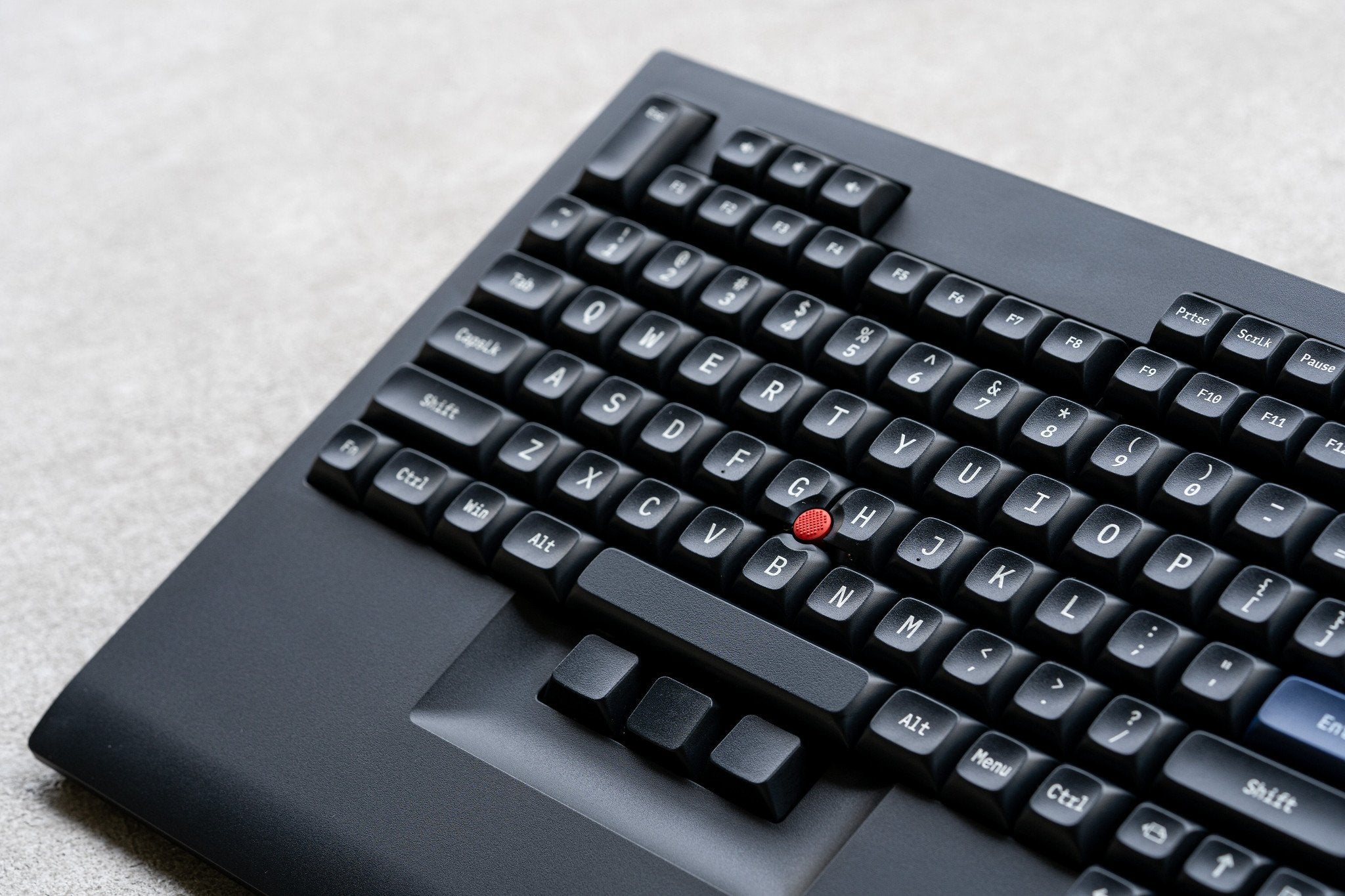
Welcome to the TEX Shinobi DIY build guide!
These instructions will teach you how to fully assemble your TEX Shinobi .
If you have any questions, please contact us (service@tex-design.com.tw)
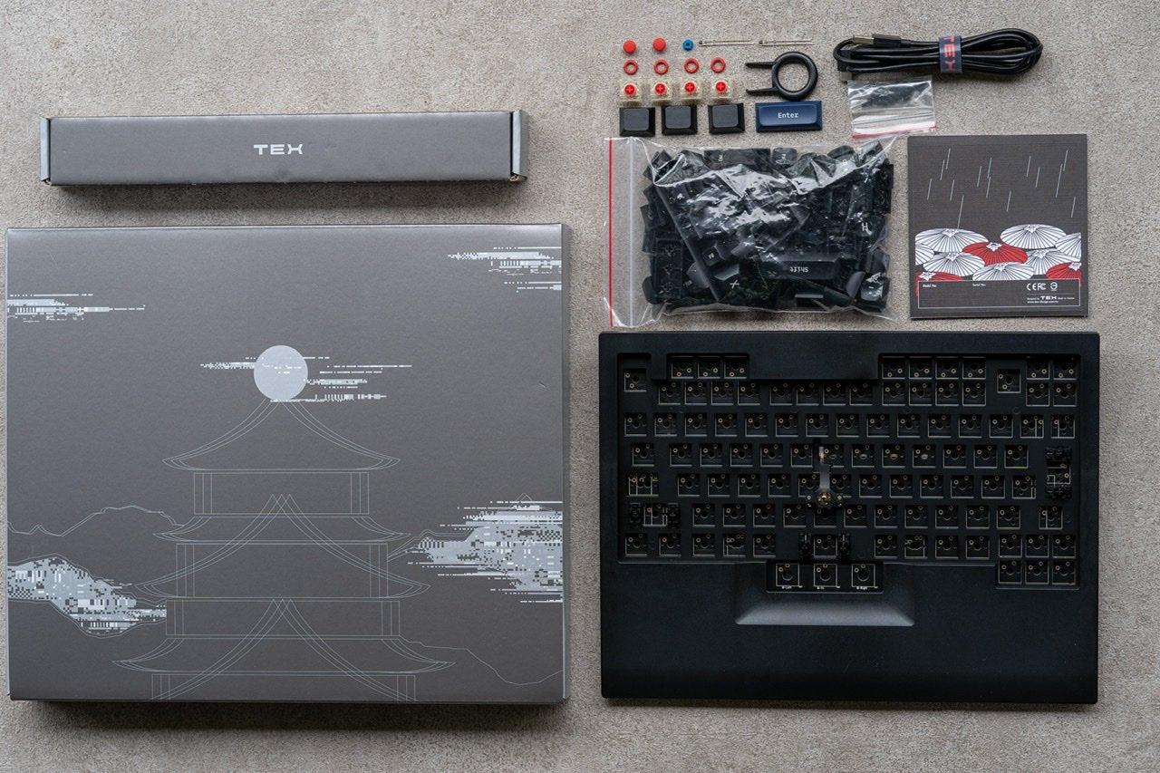
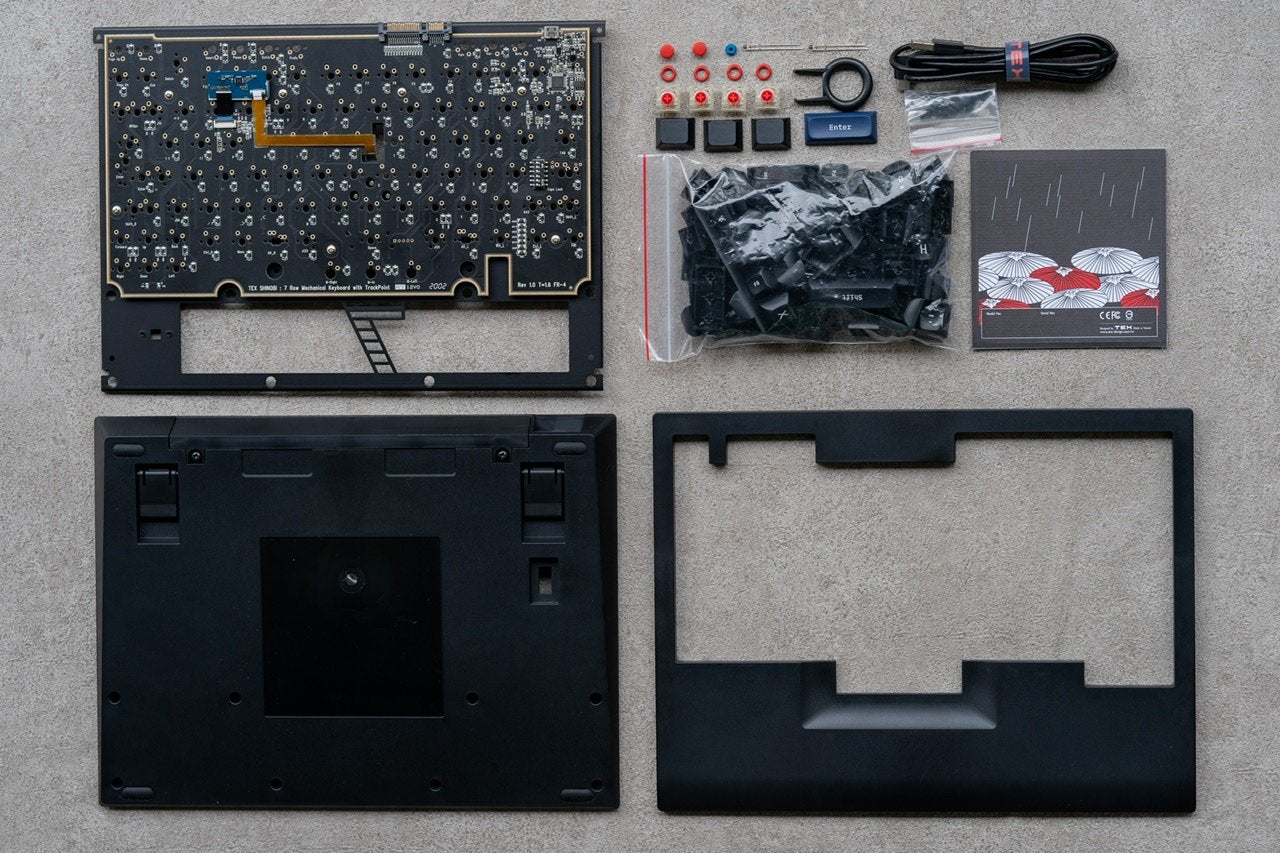
You have received a box from TEX, this is what should be in it:
- Trackpoint Module
- PCBA : support US-ASCII / EU-ISO / JAPANESE
- Keycap set : Non-Print / With print ( US/EU/JP )
- Key switch : Non-switch / With switch ( Cherry MX1A type = 100 PCS)
- Cable : 1.5 meter ( USB A type to USB Type-C )
- Metal plate : US-ASCII / EU-ISO / JAPANESE ( choose by yourself )
- Case : Top / Bottom case
- Parts:Extra keycaps / MX Low profile switch(4 pcs) / Key puller / screws / Rubber cap / O-Ring / LED ( capslock )
If you are missing components, please contact us right away.
Once you have accounted for all of the components it’s time to start the building process!


step 1
|
Plug keyboard to your computer and pretesting each key is working or not. If it isn’t working please contact us for help. # Keyboard test site
|
step 2
|
Loose 3 screws on the bottom of trackpoint module holder.
Note: Do not disassemble trackpoint module and the holder.
|
step 3
|
Install all switches and ensure that the pins on the switches are straight before you install them.
|
step 4
|
Put trackpoint module and the holder back and tighten up 3 screws on the bottom of trackpoint module holder.
|
step 5
|
Turn the PCBA back over so it is PCB side up and solder on all of the switches.
|
step 6
|
Install CapsLock LED with the long wire through the square hole and the short wire through the round hole. Solder it and then trim the wire.
|
step 7
|
Plug keyboard to your computer and then testing the switches and trackpoint module.If all goes well,stick the trackpoint PCB on the keyboard PCBA.
|
step 8
|
Put keyboard module on the bottom case and tighten up 6 screws. Screws spec:M3x5-TP3
Note: In order to avoid the screw hole stripped out, we recommended force for tightening screw is 1.5 Kgf-cm.
|
step 9
|
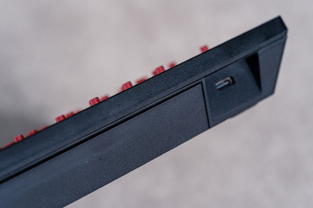
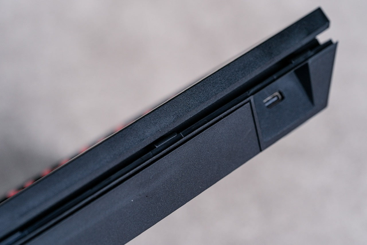
Assemble top and bottom case. Ensure that there is no gap between two of them.
|
step 10
|
Tighten up 8 screws on the bottom case. Screws spec:M3x5-TP3
Note: In order to avoid the screw hole stripped out, we recommended force for tightening screw is 1.5 Kgf-cm.
|
step 11
|
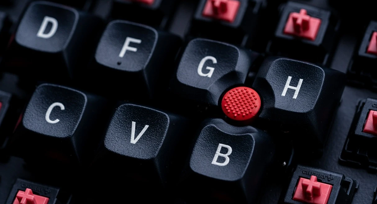
Install blue plastic cap and red rubber cap on trackpoint module.
|
step 12
|
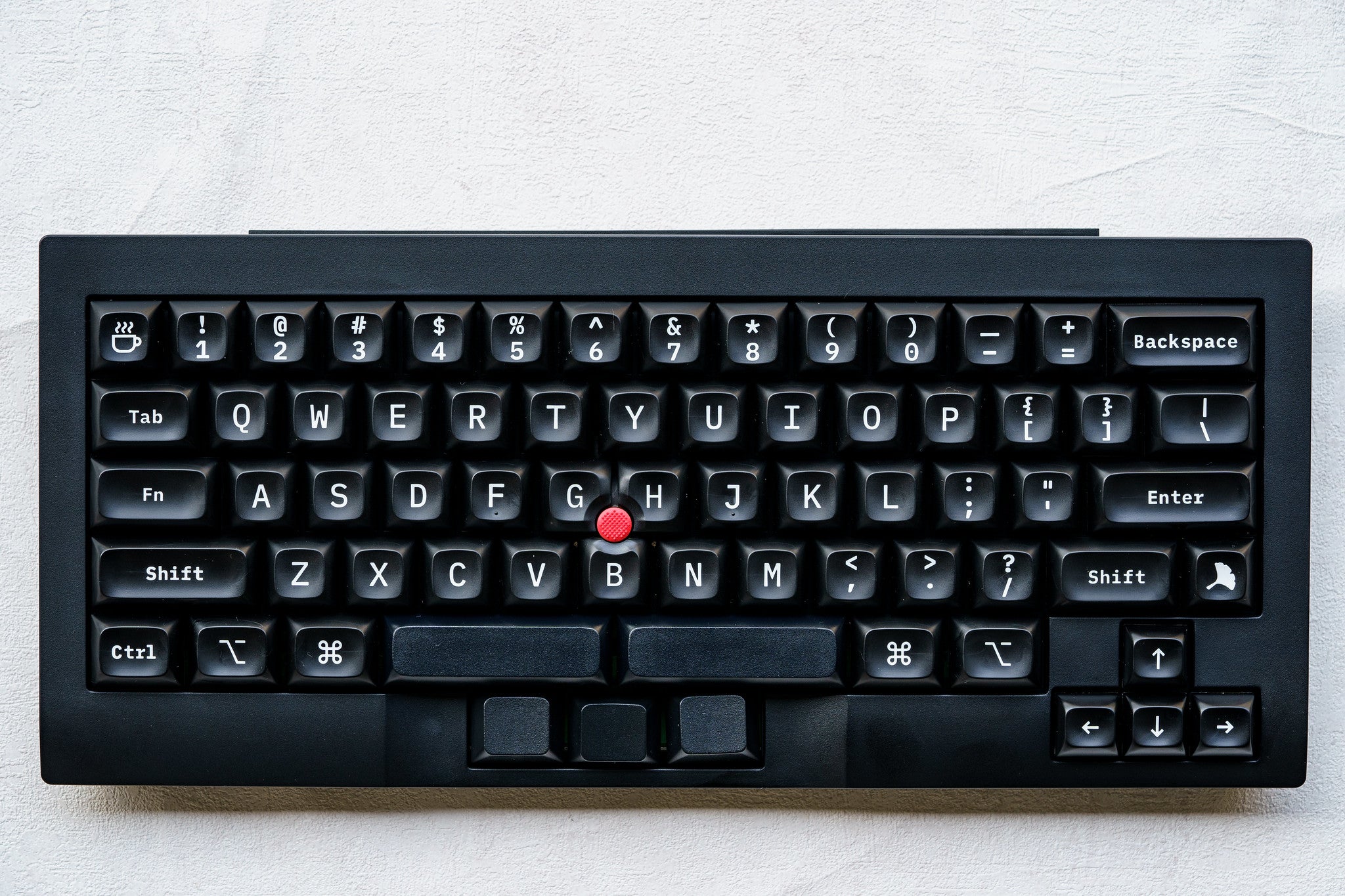
Install keycaps. For 3 mouse keycaps, we provide O-rings to reduce key stroke if needed.
|
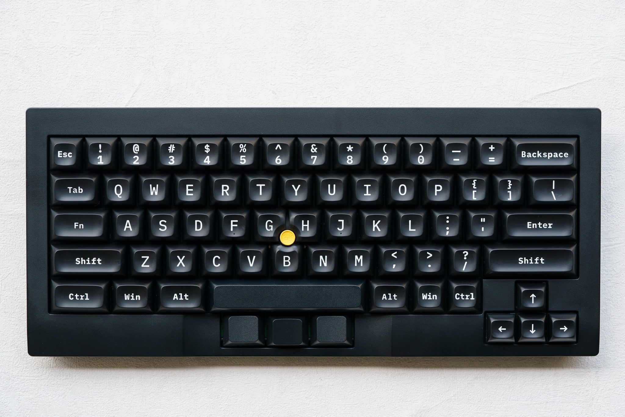
Now your TEX Shinobi is complete.
1. If you have any question , Please contact TEX service